Method 2003: Luminous Flux and Luminous Efficiency
1 Objective
Measure the luminous flux and luminous efficiency of LED device being tested under the rated condition.
2 Test Chart
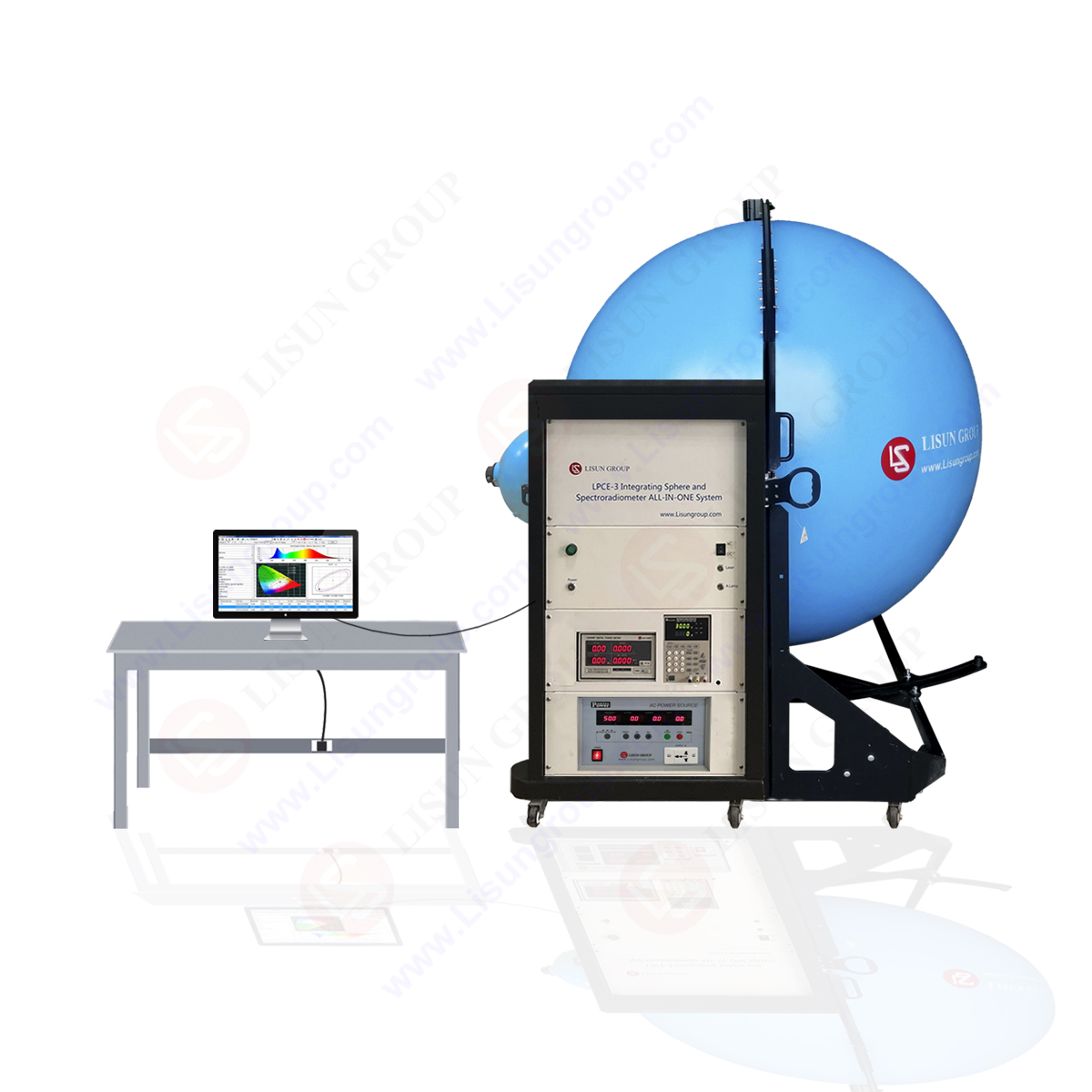
Picture 9 Method 2003 test chart
Note 1: the optical radiation lunched by the LED device under test has been reflected many times through the integral wall of the integrating sphere, that leads to uniform surface luminosity that is proportion to the luminous flux, one detector located in the integral wall measures this surface luminosity, a diffusing screen wards off the light so as not to allow the detector to directly irradiate the luminous radiation of the device under test.
Note 2: the device being tested, diffuse screen, the area of the hole compared to the ball area should be relatively small; the surface of the ball inside and the diffuse screen should have diffuse coating (minimum 0.8) of high reflectivity. The ball and detector combination should be calibrated; the peak emission wavelength and flux ( Flux Meter ) should be taken into consideration due to the power consumption of the change.
Note 3: can also use the variable Angle photometric to measure
3 Test procedures
Put the measuring devices on the entrance of the integral ball; don’t make the light go directly into the probe. Exert the rated forward current IF on the device being tested, the luminosity detection system then measures out the flux. The luminous efficiency will be obtained by using the flux value to divide the product value of the positive IF and the forward voltage VF.
4 Rated condition
Environment and tube temperature
Forward current
Tags:LED Test , Luminous Efficiency , Luminous Flux
 中文简体
中文简体


