
 中文简体
中文简体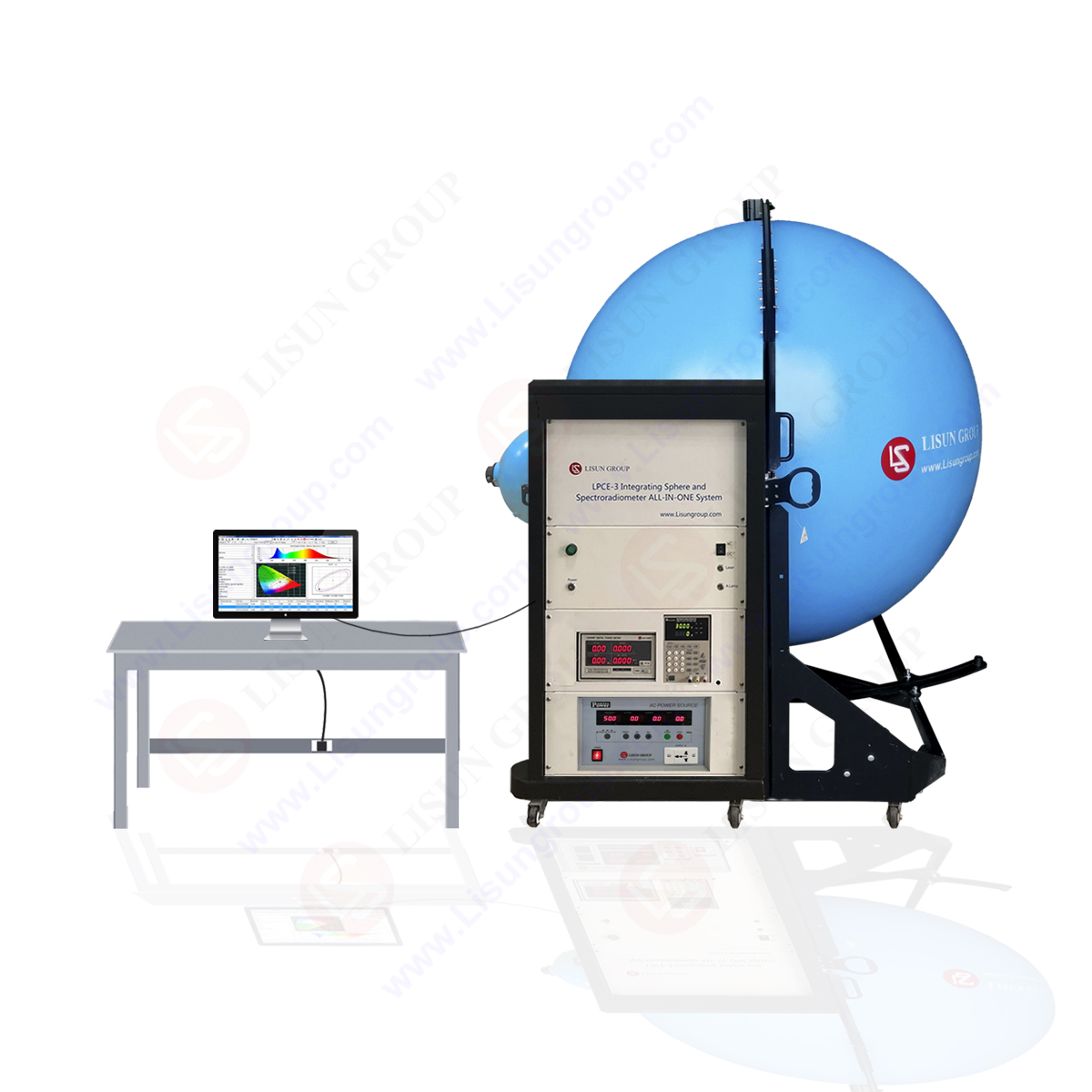


Regarding the difference between conduction and radiation tests:
Conduction test refers to the external emission of electromagnetic interference from samples through cables and various cables in the way of conduction. For example, an evaluation of the emission interference of the public power grid prevents the sample from interfering with other electronic and electrical products connected to the public power grid through the power line. The standard requires that the test be conducted in the shielding room. See the following figure for details.
The conduction test uses an artificial power network, also known as Line Impedance Stabilization Network (LISN), as the sensor between the power port of the equipment under test and the measuring receiver. It has three functions as described below.
1. Provide a stable, defined RF impedance between the measurement point and the ground reference plane, equivalent to 50 ohms μ H (or high current in 50 ohms/5 μ H) Parallel connection.
2. RF interference from each power supply phase line is coupled to the receiver while blocking the LF power supply voltage.
3. Reduce the existing external interference on the input main power supply.
Radiation test:
It refers to that the sample transmits electromagnetic interference to the outside in the form of electromagnetic wave through the air medium through the shell, all cables, internal pcb, etc. and through the equivalent transmitting antenna. It interferes with other nearby electronic and electrical products. The standard requires that the radiation test be conducted in the anechoic chamber
Radiation test: according to CISPR 22 and CISPR 11, the radiation RF measurement is usually carried out on the open area test site (OATS). Any open area test site may suffer from environmental signals generated in the neighborhood and received at the site but not sent from the EUT. These signals easily exceed the limit values of EUT transmission and many frequencies.
1. It is difficult to explain the emission map containing the environment. More importantly, it is impossible to measure the EUT at these frequencies because the EUT emission environment is covered.
2. Environmental signals can be divided into continuous narrowband, transient narrowband, continuous broadband and transient broadband.
3. A continuous narrowband signal such as a broadcast transmission can be tabulated for a given station and its frequency can be avoided.
4. The measurement is allowed in the transient narrowband environment, but the test engineer needs to know when the environmental signal appears, so does the transient broadband signal.
5. Continuous broadband interference such as pulse noise from arc welding machine is more difficult to handle, but narrowband EUT emission can be extracted by using an average detector with narrow measurement bandwidth.
6. One way to completely avoid the environment is to use a shielded room for radiation measurement.
7. Testing is usually carried out by testing laboratories with facilities for conducting and radiating emissions. These tests are usually expensive. The choice of whether to invest in these facilities will depend on the needs and frequency of testing products. They are usually used for research and development purposes.
What is the difference between conducting test and radiation test?
To sum up, the main difference is that the interference transmission methods are different. One is to transmit the interference through the cable by conduction, and the other is to transmit the electromagnetic interference through the equivalent transmission antenna by radiation.
LISUN lauched EMI receiver system for EMI (Electromagnetic Interference) radiation conduction or conducted emissions testing. The EMI-9KB EMI receiver is produced by the full closure structure and strong electro-conductibility material, which has high shielding effect. Due to the new technology for the EMI Test System, it solved the instrument self-EMI problem. The test results are according to the international format test report. The EMI Test System EMI-9KB fully meets CISPR15:2018, CISPR16-1, GB17743, FCC, EN55015 and EN55022.
System Configurations:
• EMI-9KC Test System includes: EMI-9KC EMI Receiver built-in Attenuator (9K-1GHz), LISN-A Artificial Network Power (16A with RS-232 communicate), CDNE-M316 Coupling/Decoupling Network for Emission, 3pcs Isolation Transformers and cables.
• EMI-9KB Test System includes: EMI-9KB EMI Receiver (9K-300MHz), LISN-A Artificial Network Power (5A), CDNE-M316 Coupling/Decoupling Network for Emission, 3pcs Isolation Transformers, Attenuator and cables.
• EMI-9KA Test System includes: EMI-9KA EMI Receiver (9K-30MHz), LISN-A Artificial Network Power (5A), 3pcs Isolation Transformers, Attenuator and cables.

EMI-9KB EMI Test Receiver
Lisun Instruments Limited was found by LISUN GROUP in 2003. LISUN quality system has been strictly certified by ISO9001:2015. As a CIE Membership, LISUN products are designed based on CIE, IEC and other international or national standards. All products passed CE certificate and authenticated by the third party lab.
Our main products are Goniophotometer, Integrating Sphere, Spectroradiometer, Surge Generator, ESD Simulator Guns, EMI Receiver, EMC Test Equipment, Electrical Safety Tester, Environmental Chamber, Temperature Chamber, Climate Chamber, Thermal Chamber, Salt Spray Test, Dust Test Chamber, Waterproof Test, RoHS Test (EDXRF), Glow Wire Test and Needle Flame Test.
Please feel free to contact us if you need any support.
Tech Dep: Service@Lisungroup.com, Cell/WhatsApp:+8615317907381
Sales Dep: Sales@Lisungroup.com, Cell/WhatsApp:+8618117273997