
 中文简体
中文简体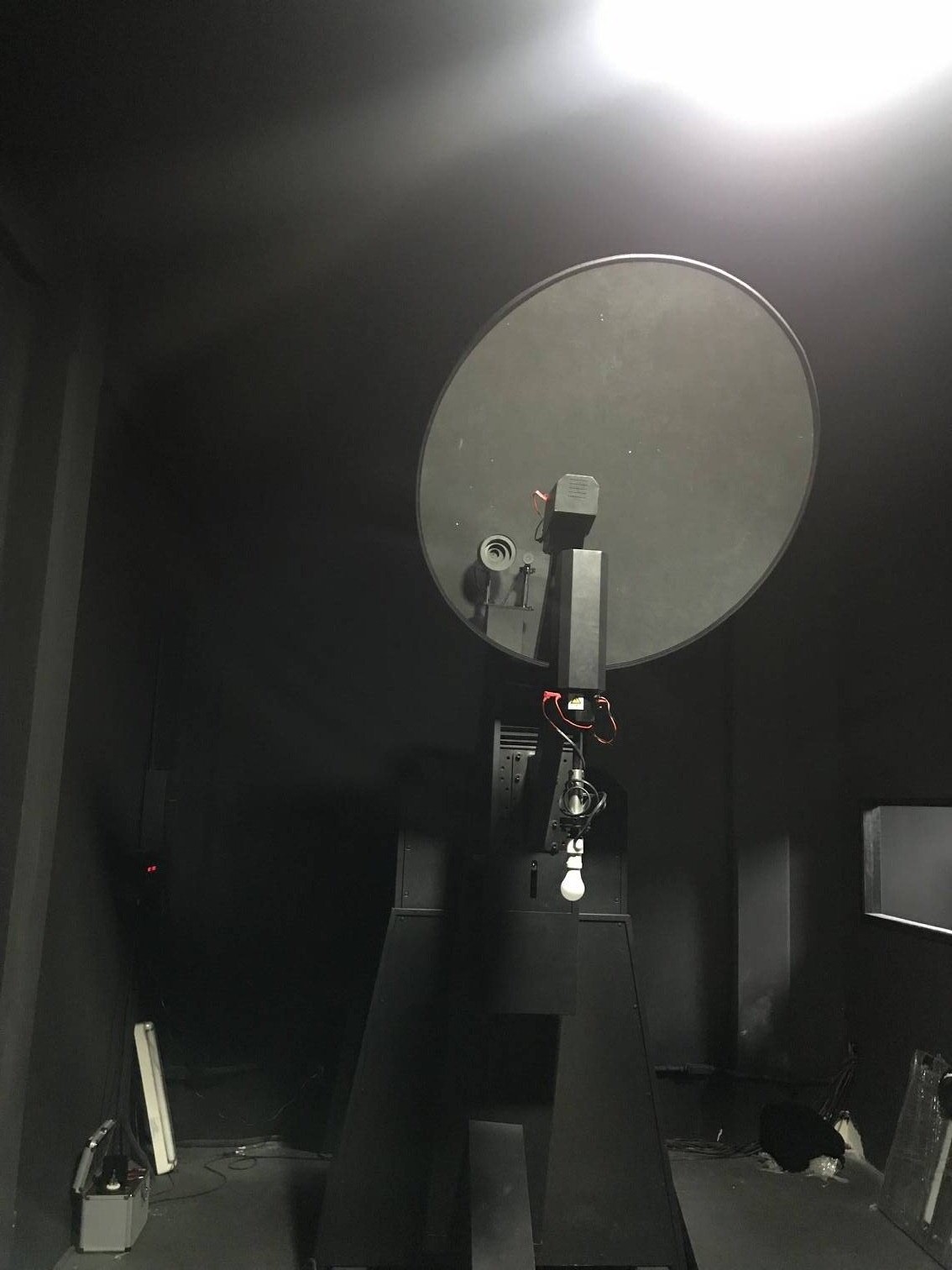

Standards GB17743-2007 / CISPR 15:2005 <Limits and methods of measurement of radio disturbance characteristics of electrical lighting and similar equipment> instead of the standards GB 17743-1999 and GB 15734-1995.
The limits for the 2m loop diameter apply to equipment not exceeding a length of 1.6m, those for the 3m loop diameter for the equipment having a length in between 1.6m and 2.6m and those for the 4m loop diameter for equipment having a length in between 2.6m and 3.6m.
According to CISPR 22: 2005 Chapter 10 specified measurement method, during 30MHz~300MHz frequency range, please check Table A to see Quas-peak of electric filed component of radio disturbance field strength. (In order to achieve reproducibility, recommend connecting the power supply with CDN, which is placed on the ground plane and terminated with 50Ω).
Table A. At 10m measurement distance, radio disturbance limits during 30MHz~300MHz frequency range.

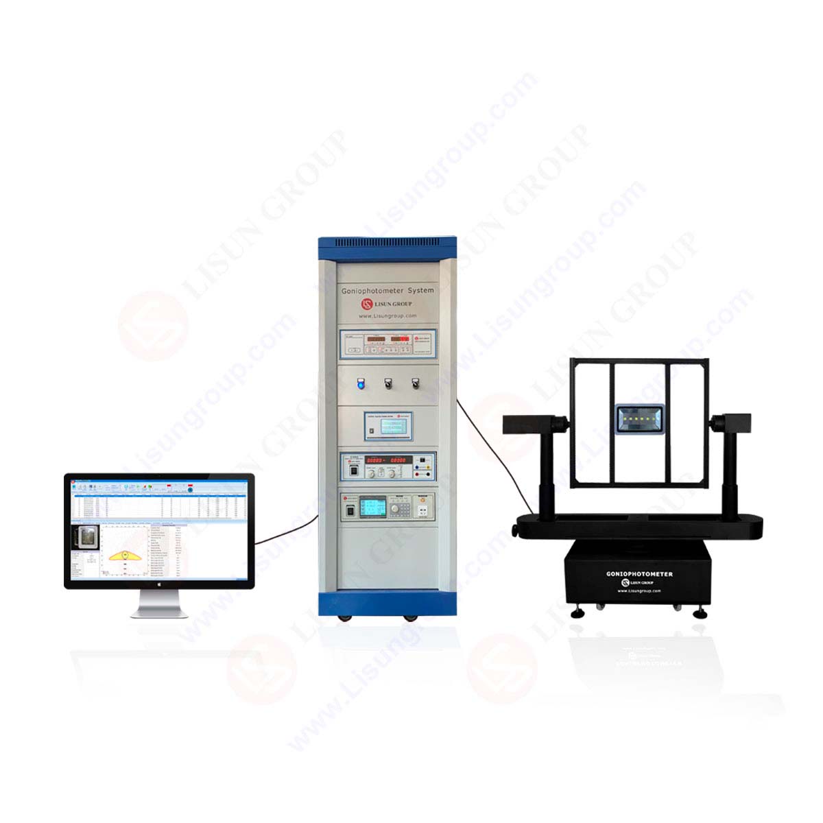
Introduce the independent method of radio disturbance measurement.
Arrange Radio frequency Emission Test:

Arrangement is shown as above. Lighting equipment is placed on one or more pieces of non-conductive wood block. Height of block is 10±0.2cm; block is placed on the grounded metal plate. The size of metal plate is at least 20cm larger than the lighting equipment.
Lighting device connect appropriate CDN with a 20±10cm power cable. Power cable should be 4±1cm distance from the metal plate. Use the non-conductive support with height 4±0.2cm. CDN is mounted on the metal plate. If lighting device has control terminals, these terminals use the same method to connect with CDN-AF2, please check IEC 61000-4-6: 2003.
The RF output terminal of CDN connects a measuring receiver with Quasi-peak detector via a 6dB, 50Ω attenuator (Require to minimize mismatch errors). If one or more CDN connect to lighting device, should measure on each CDN separately in turn. The RF output terminal of CDN which is not connected to measuring equipment should connect with a 50Ω resistance.
Measurement can be carried out in the unshielded door. The distance from conductive member should be more than 40cm.
CDN impedance parameters are provided in IEC 61000-4-6:2003.
When measure each RF output voltage of CDN, use measuring receiver with 120 KHz bandwidth and Quasi-peak detector. In CDN, RF signal is attenuated by CDN partial pressure coefficient, this value should add to the result of receiver. In addition, as there is a 6dB attenuator at the RF output of CDN, 6dB should also add to the result.
If the common model terminal voltage measured in every power cable is not exceeding the limits as below table, the lighting device is considered to meet the criteria requirements within 30MHz~300MHz frequency range.
Common mode terminal voltage limits of CDN method:
