
 中文简体
中文简体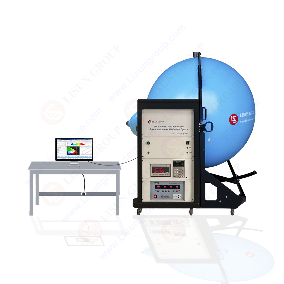

1 2000 type Light Characteristics Measuring Methods
1.1 Method 2001:Average LED intensity
1.1.1Objective
Measure the average LED intensity of the semiconductor light-emitting diode.
1.1.2 Test chart

Picture 7 Method 2001 test chart
D—LED device
G—Current source
PD–Photo detector including the diaphragm D1 with the area A
D2、D3–Eliminate the stray light diaphram D2,D3, detection solid angle should not be limited.
d–The distance between the LED device and diaphram D1
Note 1: Adjust LED device and make its mechanical axis go through the center of the detector aperture.
Note 2: The spectral sensitivity of the photometric detector within the spectrum wavelength launched by the device being tested should be calibrated to CIE (international lighting committee) standard photometric observers’ spectrum curve; Photo detector without spectral selectivity should be adopted when testing the radiation parameters. Test system should be calibrated by the standard according to the distance d and the diaphram D1. The measuring distance should be set according to the standard conditions A and B recommended by CIE. In these two kinds of conditions, the detector requires a incident aperture of the area of 100mm2 (the corresponding diameter is 11.3 mm).
Note 3: For the pulse measurement, the current source should provide the required range, width and recurrence rate. The rise time of the detector should be small enough compared with the pulse width; the system should be a peak value measuring instrument.
1.1.3 Test procedure
LED device being tested should be exerted the rated current according to the selective form. Average intensity of LED should be measured in the photometric measurement system.
1.1.4 Rated Condition
Environment temperature and suitable atmospheric conditions
Forward current, if necessary, the width and recurrence rate.
1.2 Method 2002:Half intensity angle and deviation angle
1.2.1 Objective
Measure the average LED intensity space distribution and half the maximum intensity angle and the deviation angle of the semi-conductor light-emitting diode under the prescriptive working current. Half intensity angle θ1/2 refers to the angle formed when the half intensity angleθ1/2 is larger than or equal half the maximum intensity angle, In the average LED intensity distribution graphics, the inclined angle between the maximum intensity direction (optical axis) and the mechanical axis is the angle Δθof deviation (see pasture 8).
1.2.1 Test chart

Picture 8 method 2002 test chart
D:LED device being tested
G:Current source
PD–Photometric detector including the diaphragm D1 with the area A
D2、D3–Eliminate the stray light diaphram D2,D3,, detection solid angle should not be limited.
d–The distance between the LED device and diaphram D1
θ:The inclined angle between Z axis and the detector axis.
Note 1: Distance d should be set to CIE standard condition A or B
Note 2: For the pulse measurement, the current source should provide the required range, width and recurrence rate. The rise time of the detector should be small enough compared with the pulse width; the system should be a peak value measuring instrument.
Note 3: LED being tested should be fixed in one device (such as: the center of rotation should be on the angle scale of the axis system, the angle scale should have enough angle scale precision), it requires:
–Location of LED device being tested can be accurately viewed
–Variable angle θ, device D and the center of the optical window can keep fixed.
–Can measure the inclined angle θ
–Can rotate by the Z axis of the device being tested
–Can measure the angle of rotation of X axis
1.2.2 Test procedure
a)Add the rated working current to the device being tested. Adjust the mechanical axis of the device D being tested to make it coincide with the light detector axis, namely θ=0
Measure the signal of the light detector and set this value to be I0=100%
b)Rotate the angle scale from 0-±90, use the photoelectrical measuring system to measure the luminous intensity value of each angle, and obtain the relationship of the relative intensity I /I0 and θ, give priority to the polar diagram to express together with other forms such as the rectangular graphs, and define the usage in the blank detailed specifications. Read the angleθ1 θ2 corresponding to the biggest intensity point in the chart. The half intensity angle is Δθ=|θ2 -θ1 |。. The deviation angle refers to the inclined angle between Imax and I0 direction.
1.2.3 Rated condition
Environment and tube temperature
The rated forward current IF or radiation power Φe.
Mechanical reference plane
About Lisun Group:
Lead in CFL and LED Tester. Click to our product lists:
Goniophotometer
Spectroradiometer
Integrating Sphere
Colorimeter and Photometer
LED Test Instruments
CFL Testing Instruments
EMC testing
Electronic Ballast Tester
Equipments for Testing Electronic components
Electrical Safety Tester
Environmental Chamber
AC and DC power supply
Spectrophotometer