
 中文简体
中文简体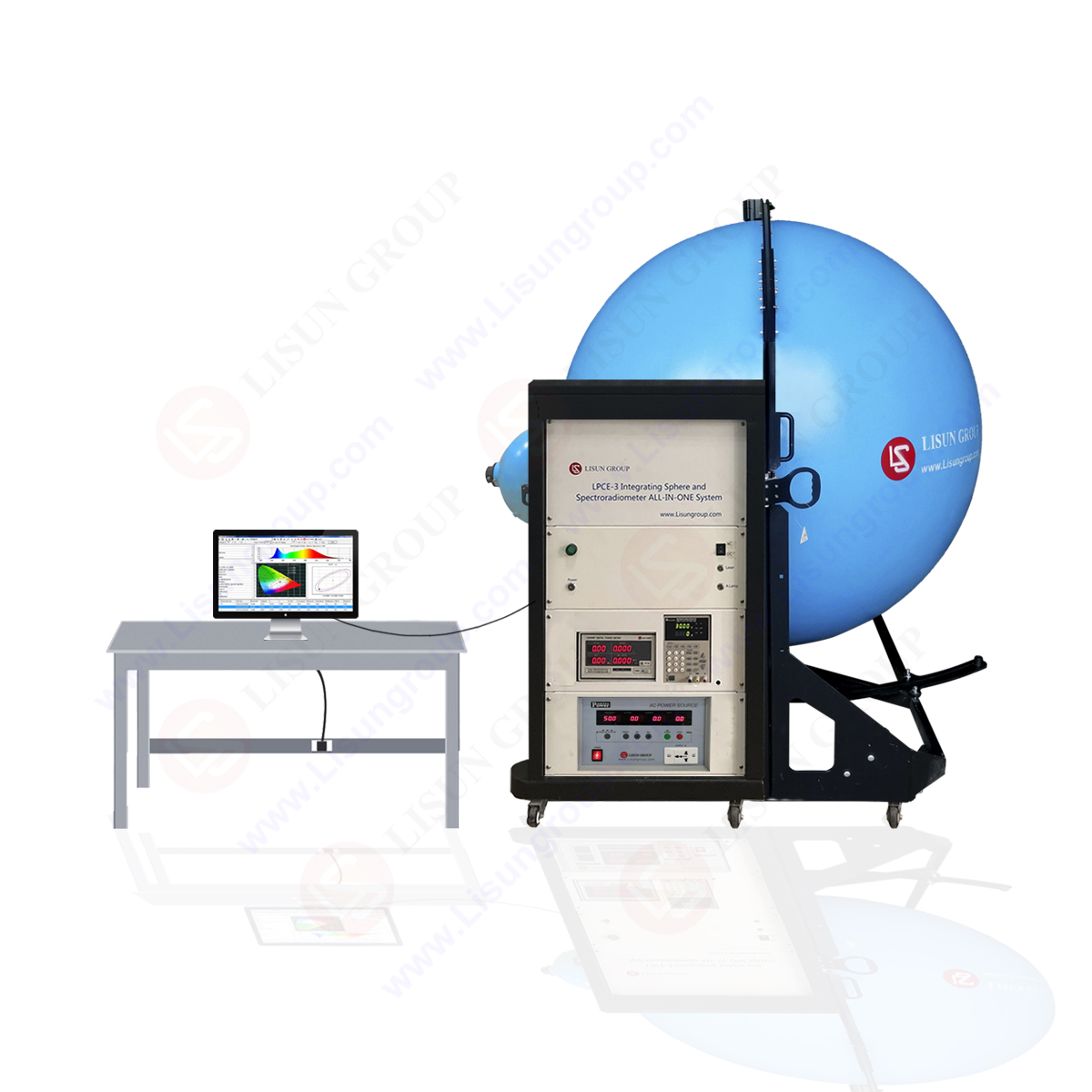

3. LED Photometry Principle
3.1 Methods of Light Intensity Measurement
The light intensity standard lamp, LED and silicon photoelectric diode equipped with V (λ) filter are installed and debugged in the optical benches, especially the filament position, LED shiny parts and acceptance scale location should be strictly debugged.
The silicon photoelectric diode should be firstly calibrated by the light intensity standard lamp. C=E/S. In this formula, Es=IS/(d 2 s)
d s is the distance between the standard lamp and the receptors, I s is the light intensity of the standard lamp, R s is the standard lamp response.
In the formula:Es=C·R t, E t is the illuminance of the measured LED, R t is the response of the measured LED. In the formula of the light intensity of LED:I t =E t ·d 2 t, d t is the distance between LED and the acceptance scale.
For LED, its shiny surface is the shape of the dome, the light distribution is very special, so under different measuring distance, the light intensity value will change and deviate the inverse distance square laws, even if the measuring distance is fixed , because the the acceptance scale of the receptors is different, the light intensity value will also change. Therefore, in order to improve the measurement precision, the measuring distance and acceptance scale should be fixed. For example, the measuring distance is recommended to be 316mm in accordance with the CIE. The acceptance scale is fixed to be 10 x 10 mm. Under the same measuring distance, different LED intersection angle has different light intensity. So in order to get the best value, it is better to read the maximum R t values.
3.2 Measuring Method of Flux
Luminous flux measurement is conducted on the turntable of the goniophotometer, LED is installed on the table, the table in the horizontal plane rotates ± 90 degrees around the vertical axis, LED rotates 360 degrees in the vertical plane around the metering axis. The intersection angle control in the horizontal plane and vertical plane can be achieved through the rotation of the stepping motor. Turntable can move freely in guide rail, when measuring the standard lamp, the turntable should leave the guide rail.
When measuring, the big wheel in horizontal plane revolves around a vertical axis, the step angle is 0.9 °, the positive direction is 90 °, and the opposite direction is 90 °. LED itself is also in rotation, in every level angle, it conducts a signal acquisition in the vertical plane every 18 °,After turning over 360 °, 20 data were collected, then the total flux ( Flux Meter ) were calculated according to the following formula.
When the big wheel rotates from 0 °to 90 °, the small wheel only needs to turn from 0 ° to 360 °. But when the big wheel rotates from 0 °to 90 °, LED installation may not be even (asymmetric) and cause error, so the best way to solve the problem is that the big wheel rotates from -90 ° to 0 ° to 90 °, the small wheel still turns from 0 ° to 360 °, The intensity of the illuminance value in the absolute equal angle, for the two ranges of 0°~90° and -90°~0° of the big wheel, takes the average value as the value in the range of 0 ° ~ 90 ° in value.
The second method of measuring the total Led flux is integral method. This method is simple and feasible, but the measurement precision is not high. The calculation method of the total flux of LED is as follows, at first, calculate the distance between the integrating sphere incident window (the incident window area A) and the standard lamp (light intensity I s), the flux of the integrating sphere Φ s, Φ s = I s. A/I 2, read the optical signal of the receiver I s, and then put LED in the window, read out the corresponding the photo-signal of the receiver. K is the color correction coefficient.
3.3 The Measurement Methods of LED Spectrum Power Distribution:
The spectrum power distribution measurement of light emitting diode aims to master the spectral characteristics and LED chromaticity, as well as to have LED luminosity amended.
When measuring the spectrum power distribution of LED, attention shall be paid to the following, in the comparison of the standard irradiance, the spectrum intensity of the standard lamp is much stronger than LED, in order to avoid this problem, it is better to add a neutral filter in front of the standard lamp to make its spectrum intensity close to LED ( LED Tester ).
The spectrum width of LED was very narrow; in order to accurately describe the spectral distribution outline of LED, it is better to use the monochromator with the narrowband wavelength to measure. The wavelength interval is 1 nm.
Calculate the spectrum power distribution of LED (E t) according to the following formula.
It is the response of the standard lamp when the wavelength is located in I ; E is the spectrum power distribution a standard lamp; i is the response when LED ( LED Test Instruments ) is in the place of the wavelength λ. The Led color coordinates calculation formula:
Color coordinates:
X = x / (x + Y + Z)
Y = X / (X + y + Z)
It can also be used to calculate the main wavelength and LED color purity.
4 Conclusions
At present, the national photometric standards for LED has established and demarcated quite a number of standard LED tubes. In this process, we have accumulated a lot of experience and then we will transmit the quality to the metrological service at all levels and the complete LED production units for the unified supervision. This has played an important role in promoting the improvement of LED quality, it has also provided the security for countries in the field of high technology research and development.
Tags:Color , Flux , Photometry