
 中文简体
中文简体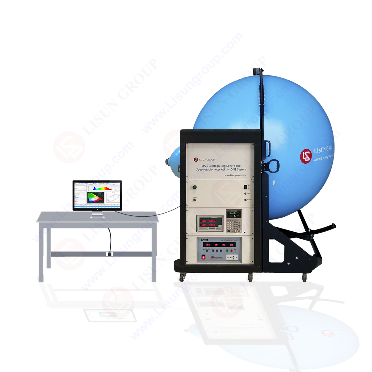


Harmonic current measuring instrument (Harmonic Analyzer)
Harmonic measuring equipment is usually composed of two parts: precision power unit and measuring instrument unit
The power supply is required to provide the voltage source with good waveform, load capacity and flat impedance characteristics.
The standard measuring instrument unit should be the time measuring instrument of discrete Fourier transform (FFT), which can continuously and precisely measure all the amplitude and phase angle of each harmonic wave.
At present, the laboratory always uses the harmonic measuring instruments which take FFT as the spectrum analysis principle. The preceding stage are the sampling circuit, module change device, the backward stage is FFT analyzer.
Test condition
This standard has stipulated the test condition of the harmonic current of some equipment.
For the unmentioned equipment, the emission measurement should be conducted under the normal working state and the maximum total harmonic current (THC) mode.
Basic countermeasures of harmonic current emission
The basic way to solve the harmonic emission condition is to add the power-factor correction (PFC) circuit in the original power circuit. Or we change the existing PFC circuit to make it meet the requirement of the test standard.
The power factor correction is usually divided into two types, namely the active and passive types.
Of course, for the small and medium-sized power electronics, electrical equipment, it is a good method to decrease the active power consumption to less than 75W. Because the standard doesn’t have the limit for the equipment of less than 75 W power (except for the lighting equipment).
Active power factor correction
Active power factor correction circuit can maximize the improvement of the power factor to make it be close to 1, which is rather ideal harmonic wave current solution.
Such a switching power supply circuit must use Level 2 switch control circuits, one level switch circuit is to control the current harmonic wave, and the other level switch circuit is to adjust the voltage.
In this solution, the circuit is complicated, and the requirement of the circuit component is high, the improvement cost is high. Therefore, we need to completely undated the design concept of the original power circuit.
We should also need to notice that the Rf transmission harassment of the power supply may increase, and then we should increase the components that restrain power transmission harassment.
Obviously, this solution should not be used in the equipment of using the linear power transformer power supply.
Passive power-factor correction
At present, the switching power supply circuit adopted by the electrical products has low switching frequency, simple circuit structure and low costs. It is a common problem that the harmonic current emission exceeds the limited value.
In this situation, the cost control may be the main factors that need to consider.
The low frequency filtering circuit may decrease the harmonic components to less than the standard limit value. This measure belongs to the passive power factor correction. This kind of solution is suitable for small and medium-sized power equipment.
About Lisun Group:
Lead in CFL and LED Tester. Click to our product lists:
Goniophotometer
Spectroradiometer
Integrating Sphere
Colorimeter and Photometer
LED Test Instruments
CFL Testing Instruments
EMC testing
Electronic Ballast Tester
Equipments for Testing Electronic components
Electrical Safety Tester
Environmental Chamber
AC and DC power supply
Spectrophotometer